


✕
I was recently sent a sketch for the system very similar to that shown in figure 1.
FIGURE 1
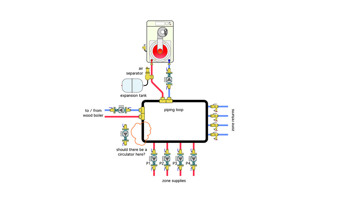
The Glitch:
When the system was operated the owner complained of flow problems. The heat emitters in any given zone were only marginally warmed when their associated zone circulator was operating. The owner questioned if another circulator should be installed in the area shown in figure 1. The rational being that the additional circulator would increase flow in the “primary loop.” Do you think this will solve the problem? Are there any other potential issues with the layout? If so, how would you propose fixing them?
The Fix
The piping loop shown in black in figure 1 is NOT a primary loop. When a given zone circulator operates some of the flow returning from that zone may pass through the closely spaced tees where the gas boiler or wood-fired boiler connect. However, if the drawing is even close to scale, much of the flow returning from an active zone will just flow in reverse back to the circulator inlet for that zone. From a hydraulic standpoint that path is shorter than the one past the closely spaced tees where the boilers connect.
I suspect that the four zone circulator were arranged as shown in figure 1 in an attempt to get the same supply water temperature to each zone. This could work – but only if the total of all active zone flow rates is less than the flow around the piping loop, which in this system is going to be essentially impossible because there’s no circulator in that loop.
Although adding a high capacity circulator to the loop could conceivably solve the problem, it’s a “bandaid” solution to a fundamental design error. A better solution is to convert the black piping loop into a header system as shown in figure 2.
FIGURE 2
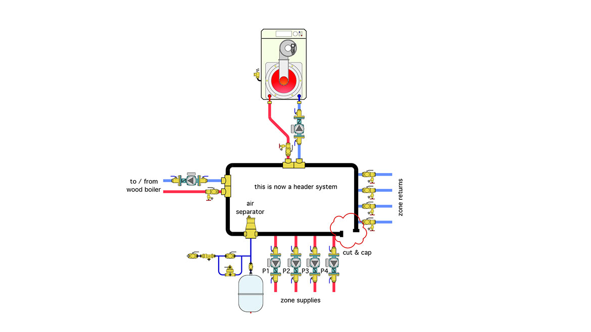
By simply cutting the loop to the right of the zone circulators, removing a short length of pipe, and capping the cut ends of the remaining piping, the loop has been covered to a supply and return header system. The zone circulators can now drive flow from the zone returns past the closely spaced tees that connect the two boilers to the system.
Other Problems: Never hang an expansion tank on its side as shown in figure 1. This puts high stress on the 1/2″ nipple of the tank. If the diaphragm in the expansion tank ever fails, and the tank fills with water, there’s a good chance the stress could crack the connection.
The air separator was initially installed on the hot side of the gas-fired boiler. That’s OK from the standpoint that the hottest water with the lowest gas solubility may be coming from that boiler. However, if the wood-fired boiler is operating as the sole heat source the location of the air separator takes it out of the main flow path. It would be better located downstream of both boiler connections in the supply header as shown in figure 2.
Finally, a combination isolation / purging valve has been added to the outgoing pipe on the gas-fired boiler just upstream of where it connects to the closely-speed tees. That valve provides a way to isolation the boiler for service or replacement. It also expedites purging.


